- #Led brightness control how to
- #Led brightness control serial
- #Led brightness control code
- #Led brightness control Bluetooth
- #Led brightness control zip
#Led brightness control Bluetooth
With evive, you normally get 115200 baud rate modules.ĭabble.begin("Bluetooth_Name") In place of Bluetooth_Name enter the name that you want to keep for Bluetooth of ESP32. For evive and Arduino Mega, Uno, and Nano:ĭabble.begin(Baud_Rate) Here Baud_Rate is the baud rate set for the Bluetooth module.
#Led brightness control serial
To enable Bluetooth communication, you have to initialize serial communication using the following code: evive, Uno, Mega, and Nano – Dabble-Arduino.
#Led brightness control zip
You can download the zip of Arduino Library for depending on the board you are using. To include the LED Control module in the Arduino program, you have to include the following header: #define CUSTOM_SETTINGSĪfter defining the above mention headers, you have to include the dabble library:

The module is made for activities like controlling LEDs.

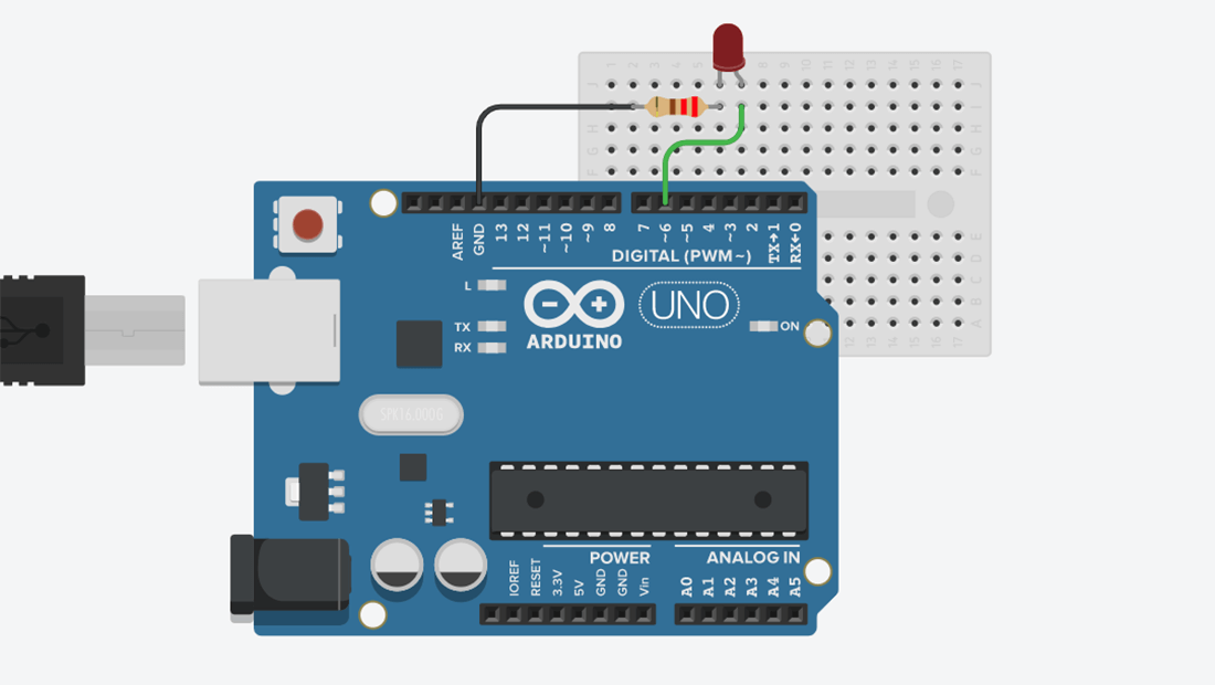
Knob range is from 0 to 100 and it is mapped to PWM values. Potentiometer type knob as seen in the image is used for controlling PWM. If the digital pin is a PWM pin then you can also vary PWM of that pin in order to get different output voltage at that pin.LED Brightness module controlling Digital Pin13. LED Brightness module controlling digital pin 13. If the pin is a digital pin with no PWM support, then you can control the HIGH and LOW state of the pin by clicking on the ON/OFF icon present in the center of the module.This module allows you to control the output of the digital pins in two ways: In the example, we will connect the long pin of the LED to digital pin 5 on the Arduino.The LED Brightness Control is the first module of the Dabble App. We will use a 220 Ohm resistor in this example.Ĭonnect the short pin of the LED to one of the GND (ground) slots on the Arduino via a breadboard.Ĭonnect the long pin of the LED to one of the PWM pins (with ~ next to their number) on the Arduino via a resistor (any value between 200 and 10k Ohm eg. Required partsġ x resistor (can be any value between 100 Ohms and ~10K Ohms). 0 is LOW (no light), 255 is HIGH (full brightness), and 127 would be medium brightness, for example. The brightness can be set anywhere between the range of 0 to 255. The analogWrite() function accepts a value (between 0 and 255) that represents brightness, rather than values HIGH or LOW.
#Led brightness control code
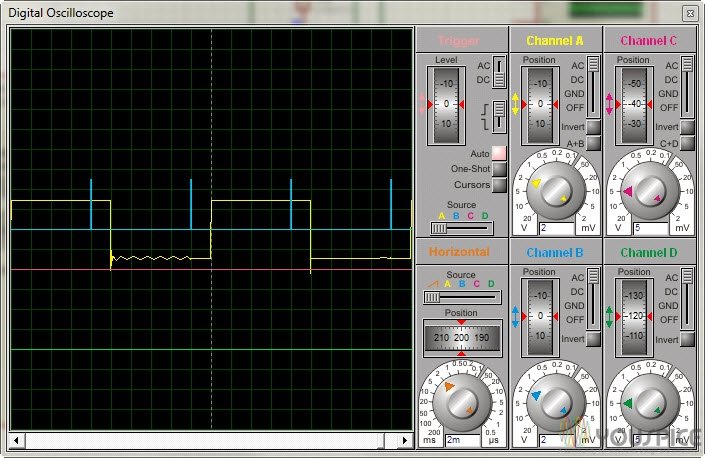
You will also need to modify your code to use the analogWrite() function instead of the digitalWrite() function. To change the brightness of your LED, you will need to connect your LED to one of the six available PWM pins. The other digital pins do not support PWM output. These pins have a ~ symbol next to their number. The Arduino provides PWM (Pulse Width Modulation) that can output HIGH and LOW at different rates to adjust the LED brightness. However, only some pins on the Arduino provide PWM.
#Led brightness control how to
In this lesson, we will look at how to use PWM to adjust the brightness of an LED.

In other words, the LED brightness is adjusted by changing the duration of lighting. This works by the Arduino repeatedly switching between the HIGH and LOW states to gradually increase or decrease brightness. However, you can use the Arduino’s PWM (Pulse Width Modulation) pins to adjust the brightness of the LED. However, digital output can only be in either of two states - off or on (0 or 1) which means that you cannot adjust the brightness of the LED using digital output. LEDs can be switched between HIGH (on) and LOW (off) states when they are connected to the Arduino’s digital pins.


 0 kommentar(er)
